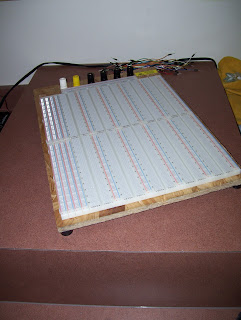
The circuit is a simple 555 timer in astable mode with a 10k potentiometer to adjust the working frequency from around 150 to 3000 hertz. The output is used to switch a tip122 power transistor which sinks a transformer that produce close to 100 volts ac. Please note that many audio transformers are potted with a low melting point wax and can get warm enough to leak and fill the holes of your breadboard!
The only difference between the circuit i designed and what i built is a 10 ohm power resistor between the emitter pin of the power transistor and ground to prevent it from sinking too much current and overheating.
The transformer im using is an old 5v wall wart transformer being run backwards.
The circuit works perfectly as expected, although since the duty cycle is not constant the voltage does increase a fair bit as the operating frequency increases.
A nice color shift from aquamarine to blue is observed when adjusting the frequency above 2000 hertz.


